The Register Window
The Register window displays the current values of CPC registers on the various support chips inside the CPC.
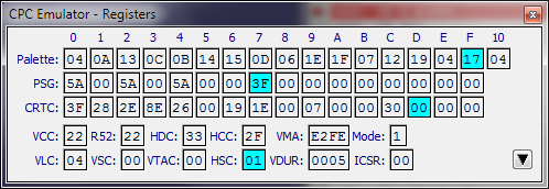
The registers are:
| Palette | The palette registers on the VGA (Video gate array). The light blue highlight shows the last selected register. |
| PSG | The registers in the PSG (Programmable Sound Generator). The light blue highlight shows the last selected register. |
| CRTC | The registers in the CRTC (Cathode Ray Tube Controller). The blue highlight shows the last selected register. |
| VCC | The Vertical Character Counter (an internal CRTC register). Keeps track of the current vertical character number. When this value equals R6 of the CRTC (vertical displayed), display output is disabled. When this value equals R4 of the CRTC (vertical total), display output is enabled and the display base address is reset. When this value equals R7 of the CRTC (vertical sync position) a Vertical Sync occurs, the display will start drawing from the top if the current VDUR value is within a threshold range. |
| VLC | The Vertical Line Counter (an internal CRTC register). Keeps track of the current raster line within the character. When this equals R9 (maximum scan line) of the CRTC the VCC will be incremented next line. |
| R52 | The Raster 52 divider counter (an internal VGA register). This triggers interrupts on the CPC. After the maximum value of 51 is reached an interrupt request is made and the counter is reset to zero. Bit 5 of this register can be reset by various events. |
| VSC | The Vertical Sync counter (an internal emulator register). When a Vertical Sync occurs this register is set to zero. When a frame flyback is active this will be displayed in light blue and count the lines in the frame flyback period. |
| HDC | The Horizontal Display Counter shows the current horizontal position on the monitor being drawn. |
| VTAC | The Vertical Total Adjust Counter is shown in light blue when the end of the current CRTC frame is reached (after VCC = R4) and CRTC Register 5 has a value other than zero. This counts up to the value in CRTC register 5 before the next frame is started. |
| HCC | The Horizontal Character Counter (an internal CRTC register). Keeps track of the current horizontal character number. When this value equals R1 of the CRTC (horizontal displayed) display output is disabled for the rest of the current line. When this value equals R0 of the CRTC (horizontal total), display output is enabled and this value is reset to zero. When this value equals R2 of the CRTC (horizontal sync position) a new scan line may be started depending on the current HSYNC position of the monitor. |
| HSC | The Horizontal Sync Counter counts the number of cycles during a HSYNC. This is shown in light blue when the CRTC Horizontal Sync period is active. |
| VMA | The Video display address. This is derived from the MA register in the CRTC, the horizontal character count HCC and the current row address (RA) register in the CRTC. This is effectively the CPC memory address of the data displayed on the monitor. |
| VDUR | The Video Display Unit Raster line (an internal emulator register). This determines the current drawing offset within the emulator display. When a Vertical Sync occurs, this register is set to a negative value determined by the current vertical position. For values between 0 and 269 (010D Hex) video data will be displayed in the emulator display. |
| Mode | The current display mode. |
| ICSR | Interrupt Control Status Register. This determines the state of pending Z80 interrupts. Bit 7 indicates that a standard CPC raster interrupt has occurred and not yet been acknowledged (eg. If interrupts are currently disabled). Other bits are used for ASIC DMA interrupts. |
The Row Highlight check box will cause the current line and column on the emulator window to be shown when in debug mode.
See ASIC Registers for information on the ASIC button.